Q: What is meant by “perimeter relief” as it relates to gypsum panel ceilings?
A: The term “perimeter relief” is used in ASTM C840, Standard Specification for Application and Finishing of Gypsum Board, and it is meant to assist in the determination and location of control joints in gypsum panel ceilings. The specific reference can be found in Section 20.3.3 where it states: “Control joints in interior ceilings with perimeter relief shall be installed so that linear dimensions between control joints do not exceed 50 ft (15 m) and total area between control joints does not exceed 2,500 ft2 (230 m2).”
That is a fairly liberal requirement for control joint spacing for the next section, Section 20.3.4., reduces the allowable area to 900 square feet. Unfortunately, the standard does not provide a definition that clarifies perimeter relief.
The intent of perimeter relief is to make the ceiling independent from the walls that form the ceiling’s perimeter. This allows the ceiling to freely move, thereby reducing the potential for stresses to build within the gypsum ceiling membrane, which leads to cracking. The source of this movement can be from various causes such as building drift or environmental changes within the structure.
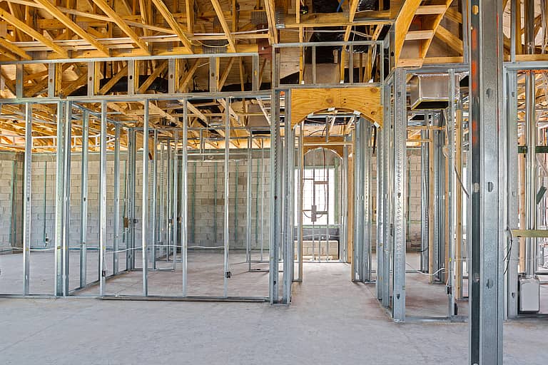
With the concept of perimeter relief now clarified, the challenge becomes how to affect perimeter relief in application. Details do exist, but they are older and reflect the use of generic ceiling grillage systems. The common generic system used steel drywall furring channels either clipped or wire-tied to a steel main carrying channel. The drywall furring channels were spaced 16 or 24 inches on center. The steel main carrying channels were typically 1 1/2 inches deep and ran perpendicular to the furring channels. The mains were spaced at 48 inches on center and were suspended from the structure with hanger wires also spaced at 48 inches on center.
The underlying theory in this detail is that there is no connection between the wall gypsum panel to the ceiling gypsum panel. It is not acceptable to use a standard joint finishing system, such as joint compound and paper tape, to aesthetically tie the two panels together. The ceiling must be able to move as needed. The details had either the wall or the ceiling terminated with a standard metallic or non-metallic trim piece as the other surface was continuous through the interface. This would create the visual appearance of a reveal around the perimeter. There was also a flexible dust membrane behind the interface to provide some closure to the joint. One interpretation at the time was that this membrane could be building paper. Currently an acceptable material may be considered as an air barrier, which provides opportunities for other materials to be used.
The described ceiling grillage system is no longer the popular choice. For many reasons the industry has transitioned to using proprietary systems that have their roots in suspended acoustical grid technology. The older generic system was an adaptation of suspended plaster ceiling systems. The challenge then becomes how to provide perimeter relief with these proprietary systems, for they don’t appear to address the concept. Details found in the various manufacturers’ literature call for mechanical attachment of the grid itself to a wall angle or “angle moulding.” The gypsum panels are also mechanically attached to this same wall angle. The wall angle is attached to the wall, thus negating any independence between the wall and the ceiling.
If the goal is the greater control joint spacing, then it should be the grid manufacturer that provides recommended details to achieve perimeter relief. If a mechanical attachment of the grid system to the wall is a requirement, it must be done in such a manner that presumably restricts vertical movement of the ceiling panels but at the same time horizontal displacement is accommodated. The finishing of the gypsum panels would also have to be altered. The applied joint finish system cannot restrict the horizontal movement. Another consideration in this condition is to develop a means to inhibit air flow through the wall-ceiling interface. The final step in the design process is to contemplate fire resistance and acoustical performance. Any gap between the wall and the ceiling is a conduit for fire, smoke and sound.
While it may be desirable to strive for the greater 50-foot control joint spacing, it may be impractical. The geometric shape of the finished gypsum area should be limited to squares and rectangles. For the rectangles there are limits on the aspect (length to width) ratio to the degree that soffit areas are restricted to a 30-foot spacing. The existence of bulkheads and punched openings for lighting and air distribution systems all impact the location of control joints. If the goal is to employ the greater control joint spacing, the reflected ceiling plan should be closely analyzed to determine if the proposed solution is obtainable.
Contractors should understand the flexibility offered by perimeter relief. However, they should consult with both the grid and gypsum panel manufacturers to assure that all design parameters of the ceiling perimeter are met to the satisfaction of the authority having jurisdiction.
Robert Grupe is AWCI’s director of technical services. Send your questions to [email protected], or call him directly at (703) 538.1611.


