Q: Can you explain the concept of thermal bridging and its current impact for the contractor?
A: Codes and standards are now looking at curbing the negative effect of thermal bridging, which will change the design of the exterior thermal envelope. This may have a great impact on the contractor when the newer codes are enforced.
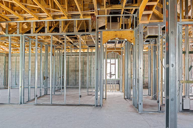
Thermal bridging, as it applies to the exterior thermal envelope, is where heat transfer through one area of the wall or roof is greater than the rest of the wall or roof. It can be a window in an otherwise well-insulated wall, or it can be far less discernible as a fastener through continuous insulation. Taking framing into account when calculating the thermal performance of a wall has been in place for years. AWCI’s Exterior Envelope—Doing It Right® course discusses the concept that the R-value of cavity insulation is greatly reduced when installed in a framed system. An example of effective R-value of the system is given where an R-11 batt, when installed in a framed wall, is reduced to 4.8.
R-value is defined as a number that indicates the amount of heat energy that will flow through a material based on its inherent heat resistance. Higher R-values results in greater heat flow resistance and better insulative characteristics. The R-value is typically for a specific thickness of the material in question. To predict the thermal performance of a given wall, the U-factor of the system is determined. This is calculated based on the individual R-values of the system components. The U-factor calculation takes into account the effect of thermal bridging.
Jay H. Crandell, P.E. of ARES Consulting Services recently gave a “Thermal Bridging: Small Details with a Large Impact” presentation for the Steel Framing Industry Association. He pointed out that three forms of thermal bridging occur in the walls of the exterior thermal envelope: clear-field thermal bridge, linear thermal bridge and point thermal bridge.
Clear-field thermal bridges are those located in the overall face of the wall. Components such as framing members and webs of concrete masonry units provide a means for the transfer of heat that exceeds elsewhere on the wall. This greater heat loss is normally accounted for in calculations to determine the U-factor of the assembly. The International Energy Conservation Code, when using the prescriptive method, has taken clear-field into account in Table C402.1.3. This provides requirements for both cavity and continuous insulation. Further, the values are specific to the exact type of structure.
Linear thermal bridges can be viewed as the interface of contiguous building components such as walls to floors. In a mid- or high-rise structure this could be where the floor slab intersects the exterior curtain wall. The heat loss is seen as a discrete line along the building thermal envelope and is calculated on a linear basis. Currently, with minor exceptions, this form of heat loss is not considered in the IECC.
Point thermal bridges occur at specific locations along the exterior thermal envelope. In residential construction, an example would be the exterior hose bib where a water line penetrates the exterior wall. Other examples would be anything that penetrates the envelope. This includes beams, columns and brackets. Similar to linear thermal bridges, this form is not part of the IECC.
While not codified at this time, there are methodologies in place to analyze and mitigate the effect of linear and point thermal bridges. There exists an analytical method to calculate heat loss, and details have been developed to minimize impact at specific locations and conditions. The use of stainless steel with lower heat conductivity is becoming commonplace. For linear thermal bridges, there are detail changes occurring around brick lintels and even where fenestration comes in contact with walls. New proprietary building products have been released to reduce heat loss in special conditions.
It is anticipated that future versions of IECC and ASHRAE 90.1 will target thermal bridges. ASHRAE 90.1, Energy Standard for Buildings Except Low-Rise Residential Buildings, is a parallel document to the IECC. Either one is adopted by individual states. All this will impact the contractors who include the exterior envelope as part of their scope of work. While the design and installation of exterior walls have been in a state of flux with the advent of energy codes, contractors should not be complacent thinking that the codes and standards have now reached a plateau. The 2021 IECC is out, and it is more stringent than the 2018 version.
Project details and specifications around potential linear and point thermal bridges may vary from the past. New and unfamiliar building products may be specified, with little room for proposed changes. Contractors need to embrace the new requirements of a code compliant exterior wall. The informed contractor will be in the best position to navigate the changes to architectural details and specifications brought on by thermal bridging and enforced by the authority having jurisdiction.
Robert Grupe is AWCI’s director of technical services. Send your questions to [email protected], or call him directly at (703) 538.1611.


